The clock sculpture tells the time using four connected systems
- lifting mechanism
- time indication racks
- track elements
- control system
The balls are transported on a lifting mechanism of three large gear wheels
Three large gear wheels transport the balls from the lowest level to the highest level of the sculpture.
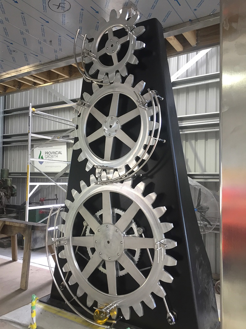
The lowest and largest gear has attachments for four balls, the middle gear has attachments for three balls and the upper and the smallest gear has attachments for two balls. Balls are raised at a constant rate of four per minute.
The balls are released from the top of the lift and roll to the uppermost time indication rack.
Timing indication racks (T1, T2, T3, T4) show the time of day by the number of balls resting on them
Next to the position of each ball in the timing racks is a number showing the seconds, minutes and hours of time the clock is indicating.
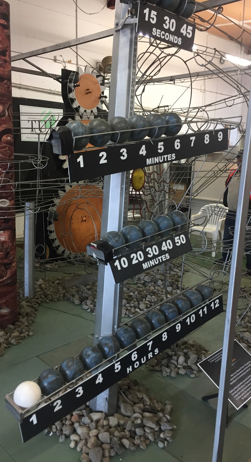
Timing indicator rack one (T1) - the uppermost rack is the one minute display, with 15,30 and 45 second intervals marked. The addition of the 60 second ball causes the rack to over balance and discharge all of the balls. One ball goes to T2 with the remaining balls going to the holding tracks.
Timing indicator rack two (T2) - the next track down is the ten minute display, with one through to nine, minute intervals marked. The addition of the tenth minute ball from T1 causes the rack to over balance and discharge all of the balls. One ball goes to T3 with the remaining nine balls going to the holding tracks.
Timing indicator rack 3 (T3) - the next lower rack is the one hour display, with 10, 20, 30, 40, and 50 minute intervals marked. The addition of the 60 minute ball from T2 causes the rack to over balance and discharge all of the balls. One ball goes to T4 with the remaining five balls going to the holding tracks.
Timing Indicator Rack 4 (T4) - the lowest rack is the 12 hour display, with 1 hour through to 12 hour intervals marked. The addition of the 13th hour ball from T3 causes the rack to over balance and discharge 12 balls to the holding tracks. One ball is permanently fixed at the one hour position to how if the time is am or pm.
Track elements
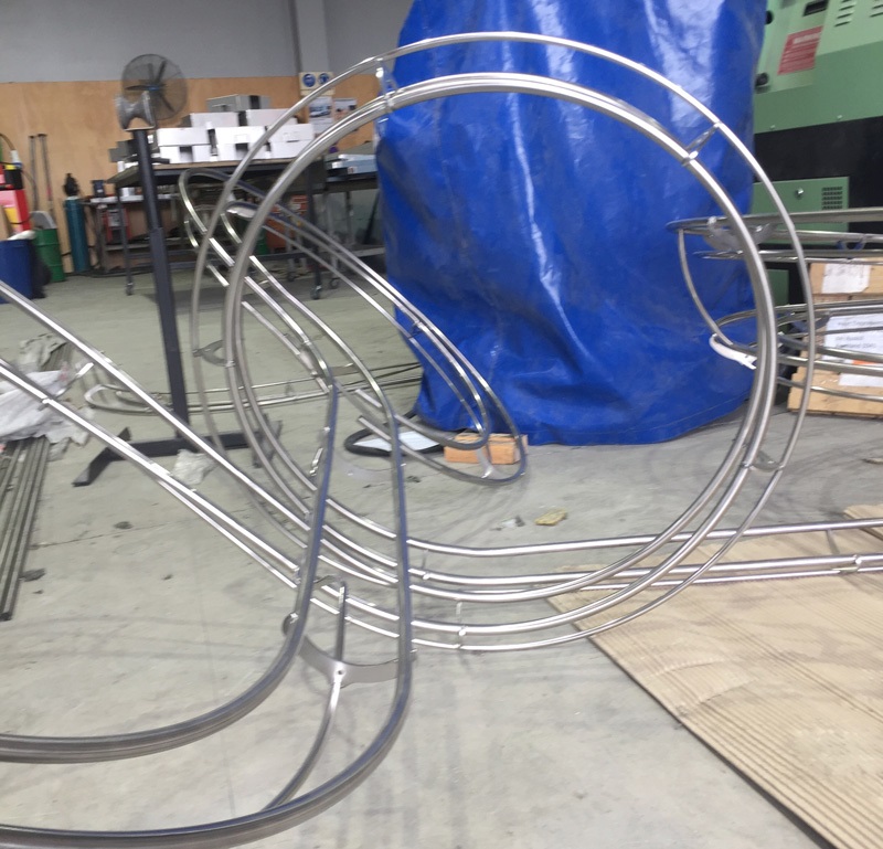
The sculpture features spirals, a Newton’s cradle, racing balls, an undulating track, a loop-the-loop, banked corners, a sawtooth track, and switches.
A clever control system ensures the clock keeps accurate time
The clock is designed to only require maintenance every six months (when a daylight savings time adjustment is made). In that six months the clock will have lifted and run over one million balls through the clock.
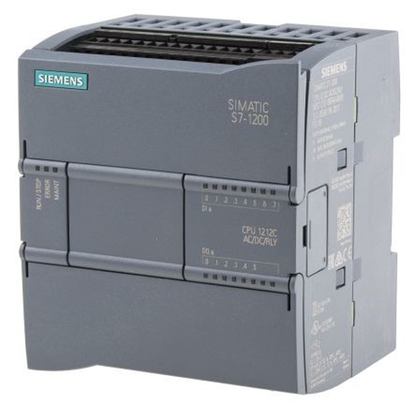
The control system is made of three main components.
The brain
The brain of the sculpture is a computer called a programmable logic controller, or PLC. This has an accurate, digital time-of-day clock, that it uses to control when the balls are released so that the correct time shows on the front of the clock.
The Cog Drive (servomotor)
The programmable logic controller controls the speed of the servomotor that rotates the clock’s main cog.
Keeping the clock accurate
There are two fine-tuning sensors keeping the clock's time accurate. The first ensures one revolution per second of the mechanism that pulls the arm causing the ticking motion of the clock's main cog.
The second detects if a ball is released every 15 seconds. If a ball arrives slightly early or late, the target speed of the servomotor's control loop will be adjusted so that the next ball is closer to the 15 second timing mark.
Design considerations
When designing the clock, minimising the wear on the balls was an important consideration. This is achieved by controlling the ball speeds by varying the track width and slope.
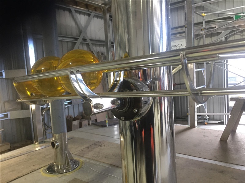
Slight changes to the track width allow acceleration of individual balls and keep the balls separated. Ball to ball contact would dramatically increase the wear and scuffs on the surface of the balls.
The balls have both kinetic and rotational energy. Reducing the track angles allows for slower balls speeds and minimises the impact when the balls are stopped.